- Details
- Category: electronicsanddiy electronicsanddiy
- Published: 10 November 2012 10 November 2012
 |
|
How to make a cheap panel voltmeter from a dollar-store pedometer.
|
The idea
After installing a small solar-panel in my shed (see DIY solar Charge Controller article) I realized that a nice addition to it would be a panel voltmeter. It's useful to keep an eye in the battery voltage to see if it is charged (or even overcharged). Of course one can buy these things online. This one from Amazon.com goes for $18 which is a bit more than I was willing to spend for something like this. Then it occurred to me that, for this particular application, I don't need a particularly fast refresh rate. The onset of winter and summer doesn't usually happen within seconds, so something that updates only every couple of seconds, or even minutes, is more than adequate to monitor a battery charge level. It occurred to me that I could use a cheap $1 PIC16F683 micro-controller to "measure" the voltage and display it using a dollar-store pedometer. The "dollar voltmeter" was born.
The 4-4-4 plan
My objective was to implement this voltmeter along my famous 4-4-4 plan. The voltmeter should cost less than $4, consume less than 4 mA and last more than 4 years. While the jury is still out on the "4 years" thing, I'm happy to report the other 4-4 objectives were met.
$4
This cost target was easy to meet since the main components (the PIC micro-controller and the pedometer) cost about $2 combined. The rest are small and inexpensive discrete components. If like me, you keep a collection of parts around in your "lab", then you probably will already have them. In any case, even if you don't here's a rough cost estimate:
BOM Cost (Jameco.com Prices)
- Dollar Pedometer: $1.00
- PIC12F683: $1.39
- 2 x BC547C: $0.16
- 78L05: $0.25
- 10 uF cap $0.10
- 2 x0.1 uF cap $0.20
- Red LED $0.12
- 5 Resistors $0.20
- Joy of making it: priceless
Total: $3.42
Hardware Design. How to Expose a Pedometer
This is the very fancy $1 pedometer I bought at my local Dollar-Tree store. Amazing how they can make these things so cheap...
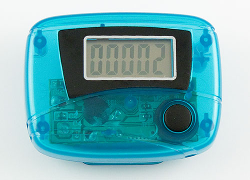
The Pedometer
Opening the thing up reveals something about it's inner workings. The device is powered from a single 1.5V button cell, so this means I'll have to provide a 1.5V supply to it (more on this later). The step counting mechanism is quite simple. When the user steps, this causes a slight vertical motion that momentarily connects the small metal piece on the top of the figure to the spring on the top of the PCB. My idea is to replicate this contact using a transistor configured as a switch activated by the PIC micro-controller. The pedometer also has a single Reset button on the front that resets the count to zero. I'll use a second PIC output and a second transistor to control the Reset.
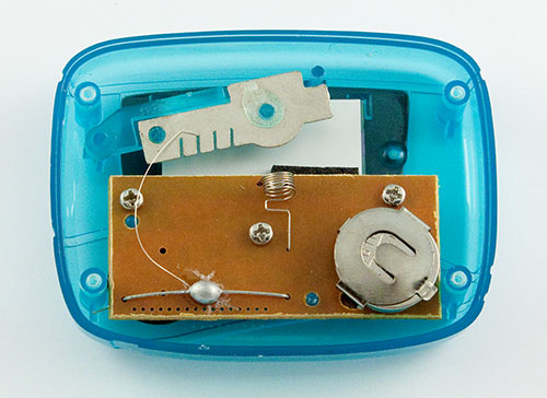
Exposed Pedometer
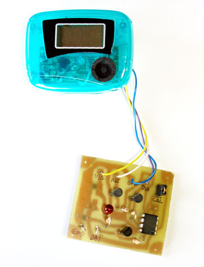
The white wire in the following photo is the "Reset" button connection. You will also need to connect the +1.5 V supply (yellow), the "Trigger" input (purple) and the ground (blue). These wires will connect to the small PIC12F683 circuit that is the core of the voltmeter (the pedometer serves only as a humble display device).
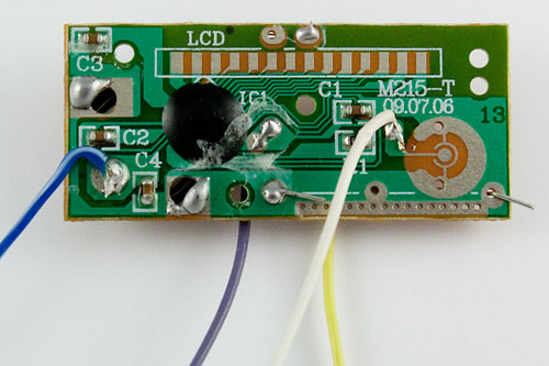
The Pedometer PCB - Front
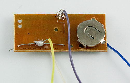
The Pedometer PCB - Back
Voltmeter Circuit
The following figure shows the final schematic for this project. The 78L05 linear regulator provides a stable +5V supply to the micro-controller. To keep cost low, I decided to use a *red* LED as a 1.5V "regulator" providing the pedometer supply voltage. In this configuration, the LED is drawing very little current (about 1.6 mA) but this is enough to maintain a relatively stable 1.5V across it. I measured the pedometer current and found it to be in the 100 micro-amp range, so the current drawn from the pedometer should not interfere significantly with the voltage regulation. In any case, this will likely be much better regulation that that afforded by a button cell that can go from 1.6 to 1.0V over its normal operation life. It is very important to use a *red* LED in this circuit as other color LEDs have different forward voltages.
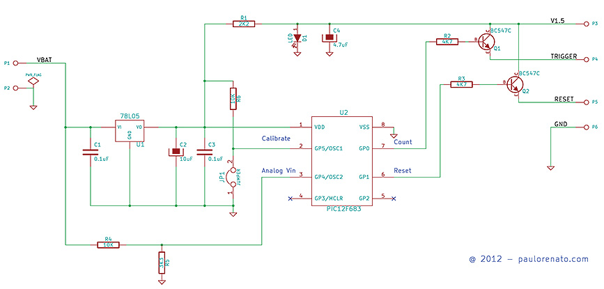
Circuit Schematic
The PIC 12F683 includes a 10-bit ADC inside that is used to measure the battery voltage. The resistive divider formed by R4 and R5 ensures the input to GP4 does not normally exceed 5V (and the current injected to the device, should there ever be a voltage surge, is limited by the series resistor R4 and the internal protection diodes). You should use 1% resistors for R4 and R5. Two "garden variety" BC547C transistors control the Reset and Trigger inputs to the pedometer. (You probably can also use 2N3904 transistors, though I haven't tested them in the circuit). The Jumper JP1, when populated, initiates a calibration procedure that you can run once at power-up to adjust the voltmeter. In this case, you will need to make sure the input voltage is exactly 2.5V at GP4. The calibration values are stored in the micro's non-volatile EEPROM.
4 mA
The complete circuit draws less than 4 mA as set out in the original 4-4-4 plan (I measures more like 3 mA typ). This is important for battery powered applications to ensure the meter doesn't drain the battery over time. With a 7Ah lead-acid battery, 4 mA corresponds to 7000/4 = 175 hours = 7.3 days. Since the solar panel charges this same battery every day, there is no danger of the voltmeter draining the battery in any significant way.
Software
The software was written in PICBasic Pro. The .hex file can be downloaded [AT THIS LINK]. When you first power the device, you have an option (fully optional) to calibrate the meter. The software detects this by determining whether the JP1 jumper is installed or not at power-up. You should in this case power-up the device with an input voltage of exactly 12V (use a lab supply and a multimeter). The software signals calibration by blinking the display 3 times. It then proceeds to take 8 measurements, average them out to avoid noise issues and compare the result against the expected value. The calibration offset is stored in EPROM for normal use. The display will then blink 5 times to indicate the calibration ended. The device should now be powered off and the jumper removed.
During normal operation (no jumper installed), the micro-controller takes a reading every minute (this is adjustable in the software) and after doing sample averaging and filtering (median filter to discard "out there" measurements) and make sure no noise interfered with the measurement, it increments the pedometer one step at a time until it reaches the measured voltage. It finally puts the microprocessor into sleep mode until the next measurement cycle.
Note that here is no decimal point in the pedometer display. For example, a measurement of 12.5V is displayed as "125". Naturally, this is a very slow "refresh" rate for a voltmeter, but for monitoring a solar lead-acid battery, it is quite acceptable, since variations tend to occur in hours or even days. For a faster update but with a coarser resolution, one could change the code to drop one digit so that the same 12.5V measurement in the example above would be displayed as "12", thus requiring only 12 "increment" steps. I also discovered experimentally that you can only drive the "trigger" signal in the pedometer so fast. This was actually one of my first experiments in a breadboard. As expected, these pedometers have some sort of "de-bouncing" programmed so that very short consecutive pulses are ignored. This limits the maximum increment speed one can apply to the voltmeter. The code toggles the pedometer "trigger" about as fast as it can without missing pulses.
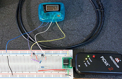
Testing an early prototype
Building it
As shown in the figure below, you need to drill (or melt) a small hole in the back of the pedometer to pass the control and power wires. These wires then connect to the main control board.
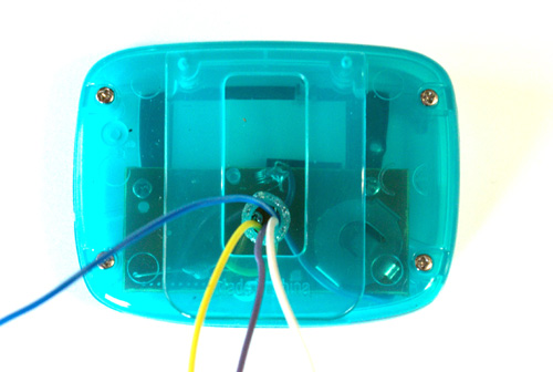 Wire escape route
I designed a small pcb to house the circuit though, given its simplicity, it can also be easily implemented in a prototype board. The following photos show the final assembly (minus the enclosure).
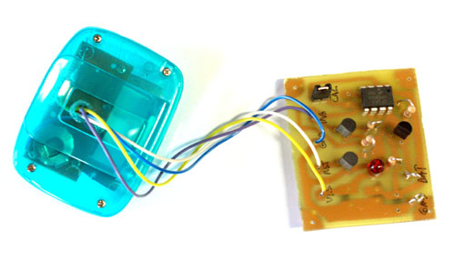
PCB and Pedometer, View 1
PCB and Pedometer, View 2
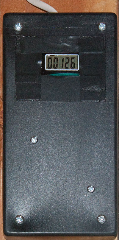
In many applications you might not even need an enclosure. In my case however, I decided to use a small plastic box I had laying around to give it a more "finished look". This is the final result. Note the 12.6V measurement ("126" display value).
Enclosure
Results
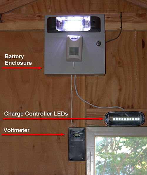
The photo below shows my shed solar installation that is comprised of 5W solar panel (not in the photo) charging a 12V Lead Acid battery inside the white box through my DIY solar Charge Controller. The power harvested by the system, drives a motion-activated LED lamp for lighting the shed. Notice the "Dollar Voltmeter" at the bottom:
Le Shed
4 years?
So the only question remaining is: will it last 4 years? Well, hopefully I'll be able to tell you this some day in the future. In the meantime, the device has been working perfectly for a couple of months already, with temperatures often exceeding 100F under the sunny California sun. So far, the "Dollar Voltmeter" is not letting me down. See you in 4 years...
Comments, questions, suggestions? You can reach me at: contact (at sign) paulorenato (dot) com