- Details
- Category: electronicsanddiy electronicsanddiy
- Published: 31 July 2014 31 July 2014
 |
|
An Excel-based, common-emitter and common-collector transistor amplifier calculator for high-frequency operation.
|
Common-Emitter and Common-Collector Transistor Amplifier Calculator for High-frequency Operation
Analysis of the bipolar transistor amplifier at low-frequency is relatively easy, and several calculators exist online that do a good job. For high-frequency operation, there are fewer references available. For my projects, I like to build a reference spreadhseet where everything is in one place. This allows me more flexibility in optimizing the circuit, and is much faster than simulating with LTSpice or similar package. Furthermore, constructing such a tool is a great way of gaining more insight into how the circuit works, and how each of the parameters affects performance. The two amplifier circuits covered in this spreadsheet are depicted in Figure 1 and 2. Figure 1 is the Common-Emitter amplifier and is useful for relatively high gain applications with moderate input and output impedance. The Common Collector circuit in Figure 2, has a gain close to 1 and is useful as a buffer circuit with its low output impedance and moderate to high input impedance.
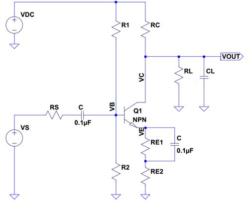
Figure 1 - Common Emitter Circuit

Figure 2 - Common Collector Circuit (Emitter Follower)
The Spreadsheet
The spreadsheet can be download through the link below:
 |
Transistor Amplifier HF Calculator, Rev 2 |
And here's an Excel 2003 compatible version as some users can't open the latest excel formats.
|
Transistor Amplifier HF Calculator, Rev 2 (Excel 2003 compatible) |
The spreadsheet is divided into two worksheets (tabs), a "About" spreadsheet with some help, and a "Calculator" spreadsheet where the "meat" is. Figure 3 shows a screenshot. The fields in green are inputs. Not all inputs are needed depending on what your intent is when using the spreadsheet. For example, if you are only interested in Bias calculations, the capacitances are not required. Most of these values can be extracted from a standard transistor datasheet. The orange coloured fields are automatically calculated.

Figure 3 - Calculator Interface
For convenience, the spreadsheet also includes a list of standard resistor values and the two diagrams from Figures 1 and 2 above. See Figure 4.

Figure 4 - Convenience Features
Note that some of the results and calculations are approximations. The noise analysis is a simplified version of the one I used in the resistive feedback transistor calculator article for example. The spreadsheet is intended to provide a first-order approximation, but more analysis using simulation and a "real" circuit prototype is recommended before committing the circuit to a board.
Comments, questions, suggestions? You can reach me at: contact (at sign) paulorenato (dot) com
